1.Add Boolean operation function in Interior Modeling 2.0
Boolean Operations create a new model by conducting Subtract/Union/Intersect operations of more than two groups of models. We have offered three methods for Boolean Operations: Subtract, Union, and Intersect. You can make more complex models through Boolean operations (*Note: Boolean operations only support a single fully closed group model, currently only 1-to-1 Boolean operations are supported, and operations are not supported for multiple grouped models.)
Instruction:
Subtract: Subtract the part of the A model that overlaps with the B model.
1) Create two models, both of which need to be combined separately (shortcut key for combination: ctlr+g)

2) Select "Subtract" on the top toolbar, and then select model A and model B in turn and you will get the following shape.
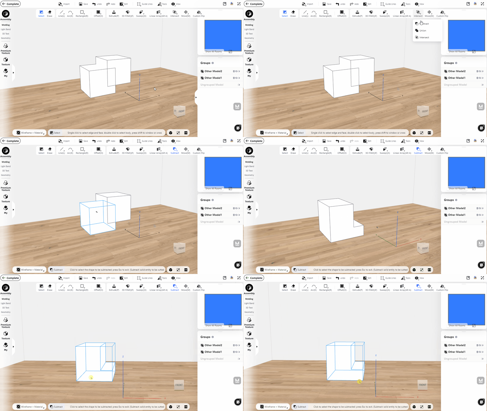
Union: When two models intersect, the intersecting part will be deleted, and the two models will become one model after the operation is completed.
Repeat the first step above, select "Union" on the top toolbar, and then select model A and model B in turn and you will get the following shape.
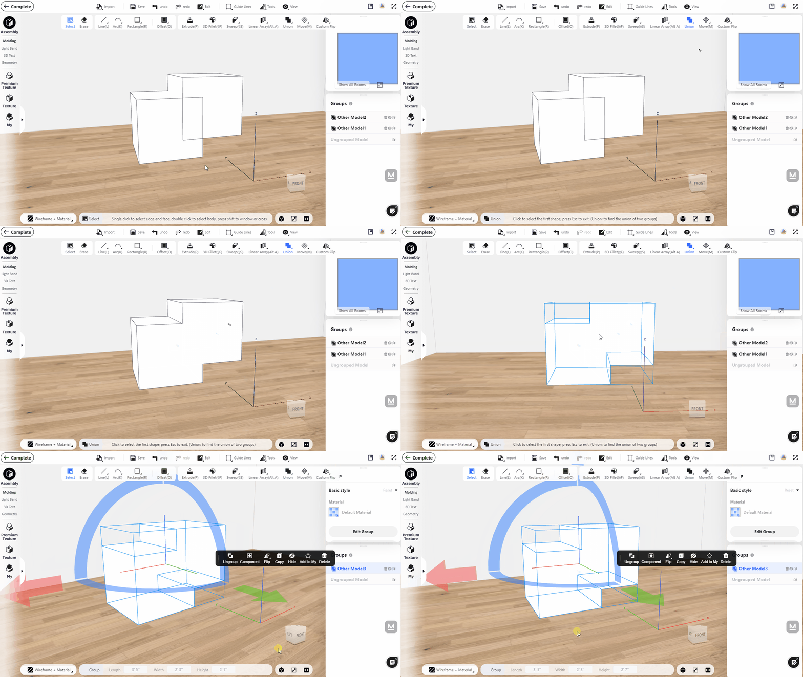
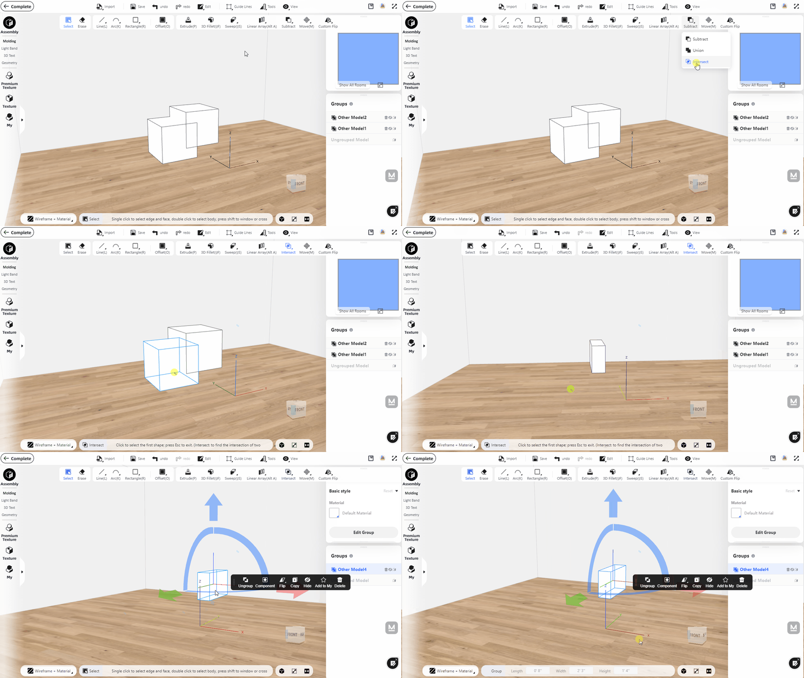
Intersect: When the two models intersect, the intersecting part will be retained, and the disjoint parts will be deleted to obtain a new model.
Repeat the first step above, select "Intersect" on the top toolbar, and then select model A and model B in turn and you will get the following shape.
2.Add Batch Operations of Extrude, Ungroup and Subtract in Interior Modeling 2.0
In the modeling process, "Extrude", "Ungroup" and "Subtract" are frequently used modeling functions. Batch operations can save a great amount of modeling time.
Instruction:
Batch Extrude
1)Hold the "Shift" key and multi-select (or box-select) the faces you want to extrude.
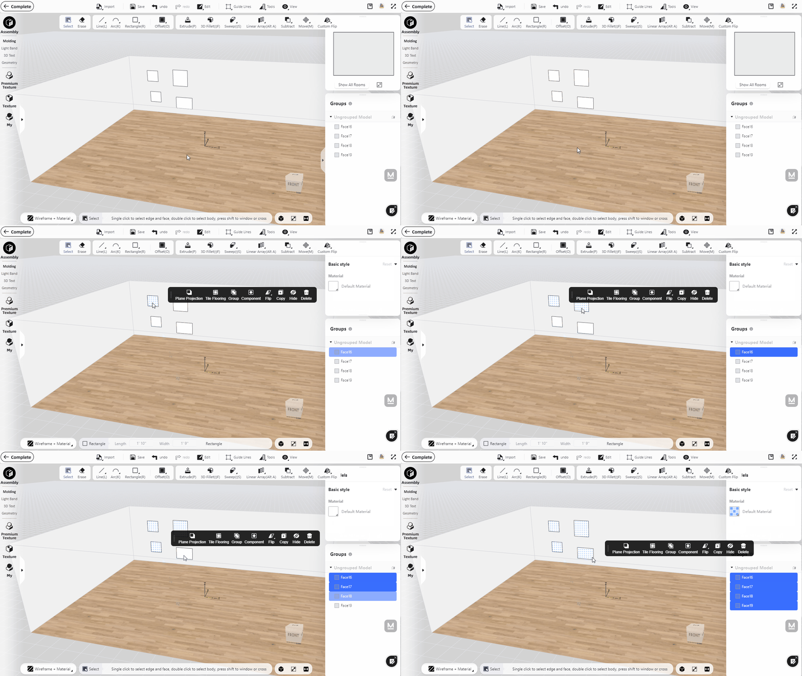
2)After selection, click ''Extrude" from the top toolbar to do the batch extruding.
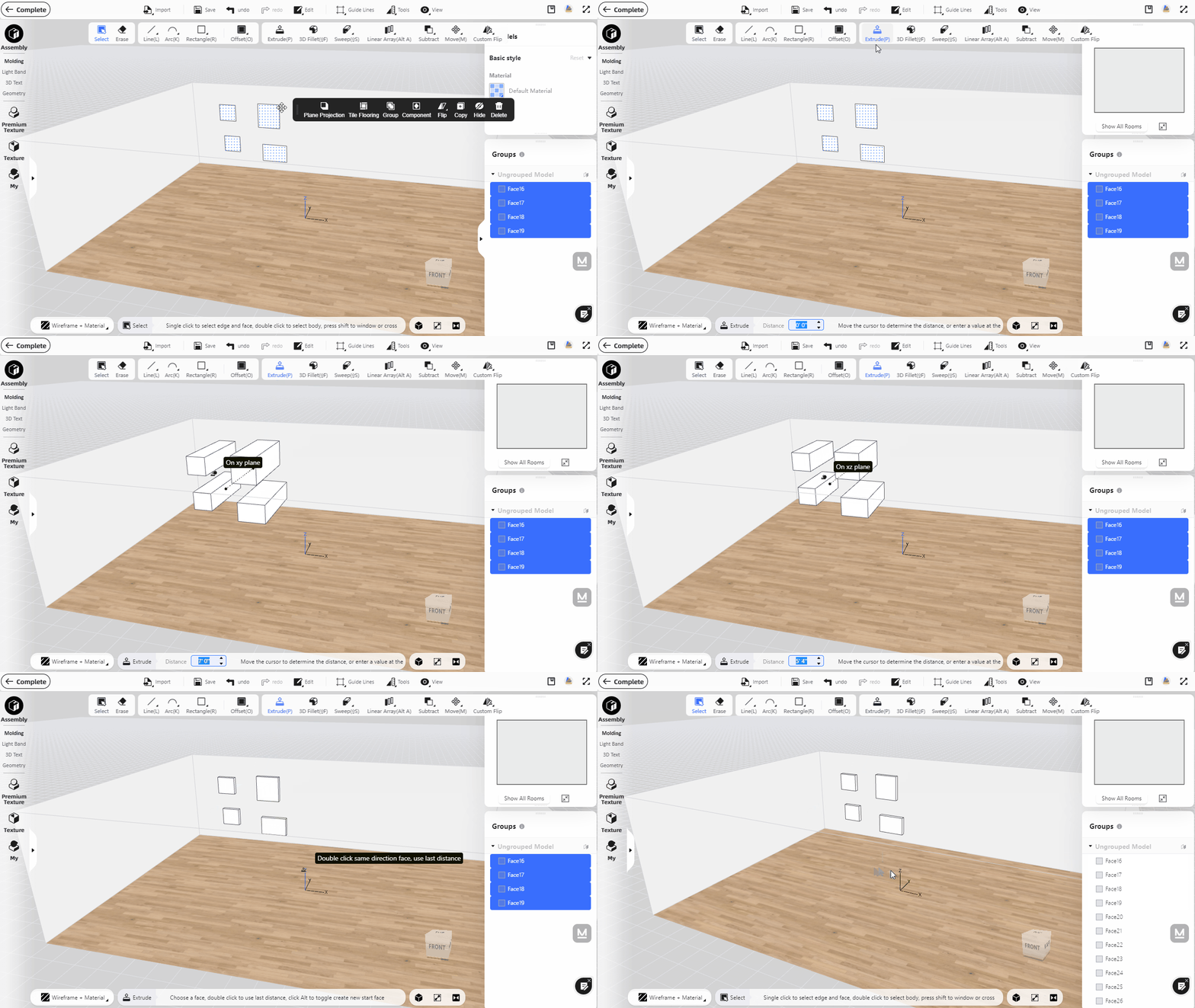
Batch Ungroup
1)Hold the "Shift" key and multi-select (or box-select) the faces you want to ungroup.
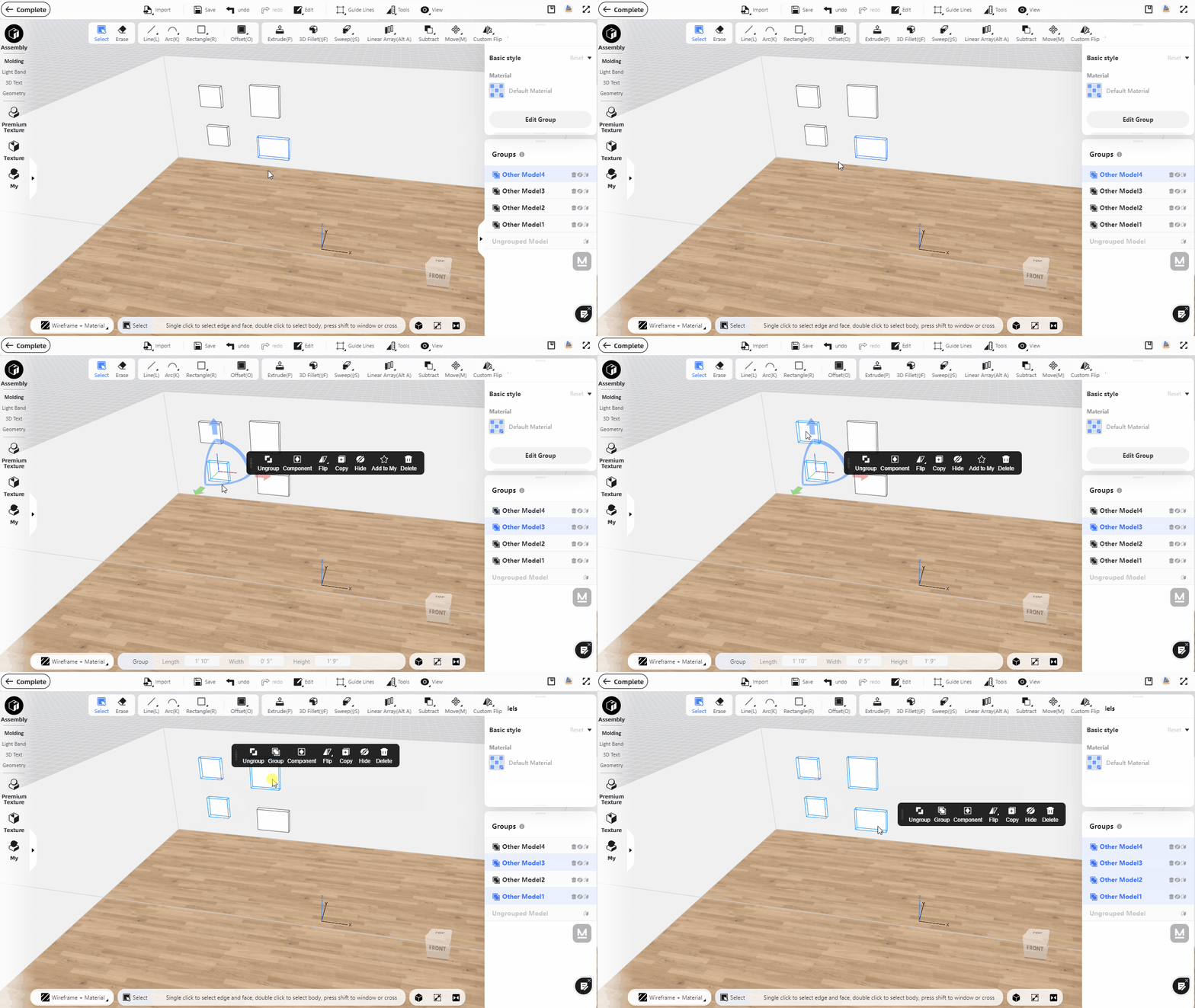
2)After selection, click "Ungroup" to bath ungroup the shapes.
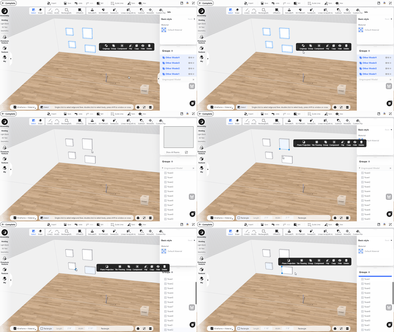
(*Note: In the case of the grouped models with multiple level grouping, batch ungroup operation can only ungroup the uppermost level.)
Batch Subtract
Take the pegboard modeling as an example:
1)Creat a cylinder, double click and "Group" it, which will form a groped cylinder model.

2)Duplicate the grouped cylinder to make a cylinder array (with linear array command, or simply copy and paste with shortcut keys Ctrl+C and Ctrl+V). Afterward, hold the Shift key to multi select all cylinders, then group again.

3)Create a cuboid as the board base and group it, then adjust its position and the cylinder group.

4)Click the "Substract" command from the top toolbar. Select the bottom cuboid first, and then select the cylinder group to execute the Substract command (to let the cuboid to subtract the cylinder group).

5)You will get the following model after the boolean operation:

Note:Unlike Subtract, the Union and Intersect commands now only allow one to one operation between single grouped object (unlike the cylinder group in the example above).
3.Add "Image Recognition" to automatically generate image contour in Interior Modeling 2.0
Interior Modeling 2.0 now supports identifying uploaded image content, converting it into lines and surfaces, and importing it into interior modeling for editing, which is convenient for designing logos, graphics and other elements.
Instruction:
1)Select "Import-Image recognition" on the top toolbar. Then click the left mouse button to select the surface where you need to place the shape, and the image import interface will pop up (please read the image requirements in detail before importing to avoid failure).
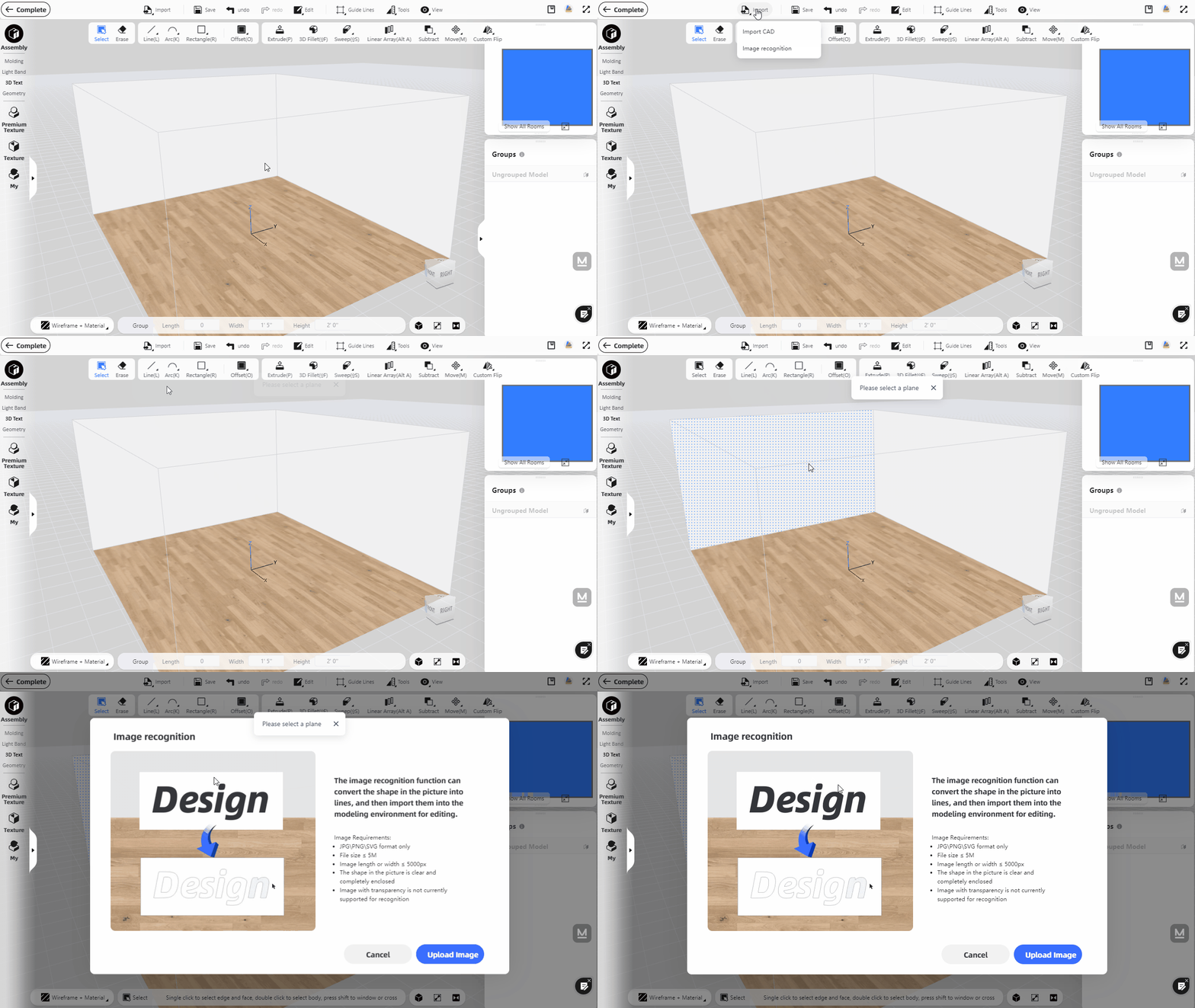
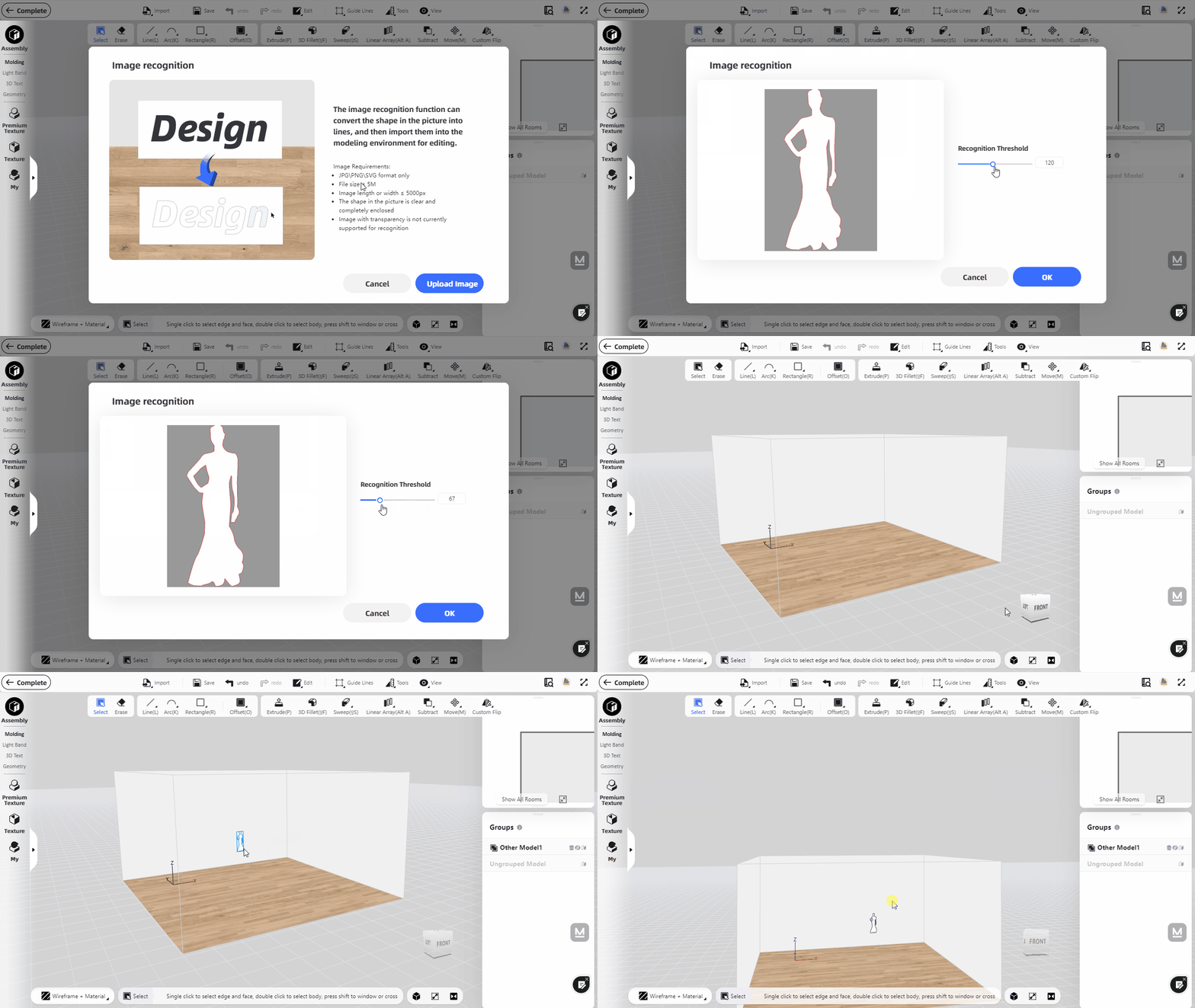
2)Click "Upload Image", select the image you need from your computer. You can adjust the value of "Recognition Threshold" in the import panel. After the adjustment is complete, click OK, and the image recognition is completed. Click on the face to place the recognized shape.
4.Support attaching 3D text to arc surfaces
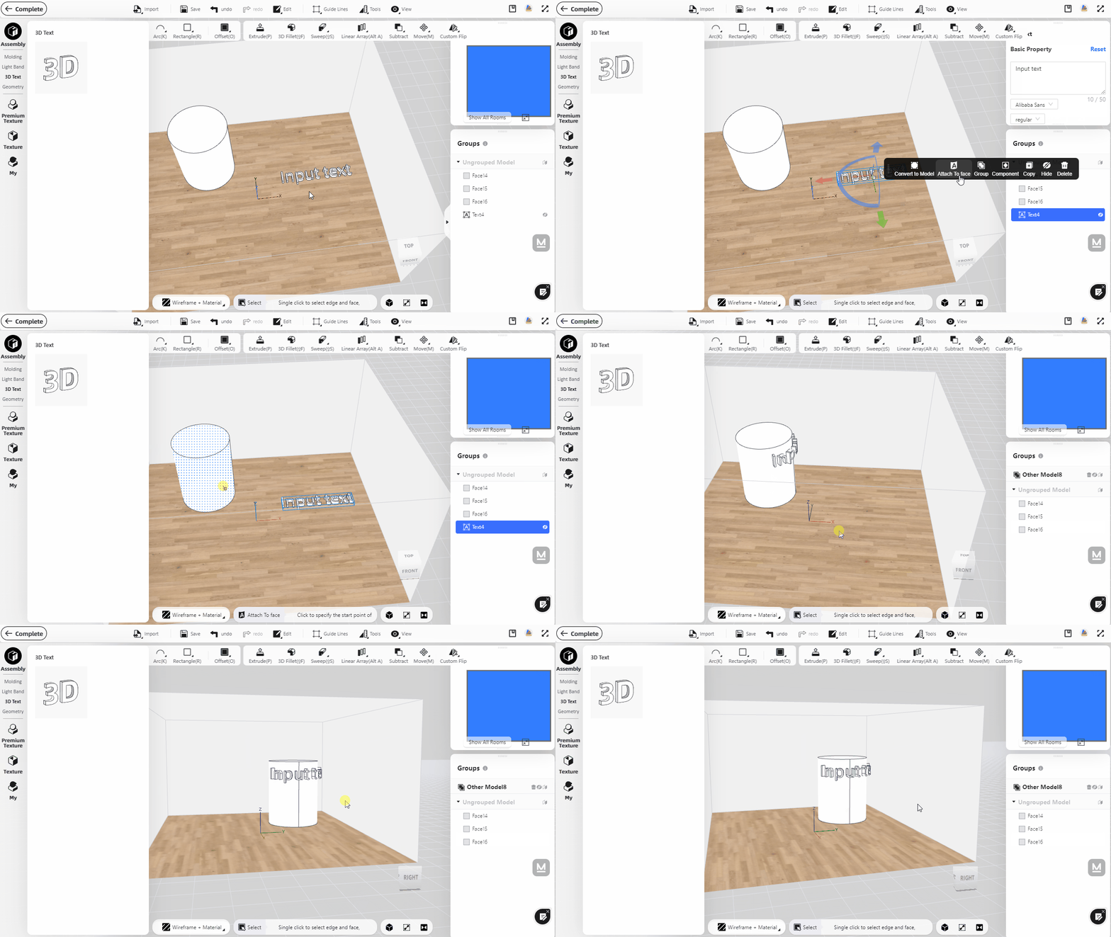
3D text created in Interior Modeling can be attached to the surface model to meet different design requirements. (Note: "Attach To face" currently only supports flat or arc surfaces, but not complex curved surfaces)
Instruction:
1)Select the “Assembly-3D Text” on the left catalog to add text to a face.
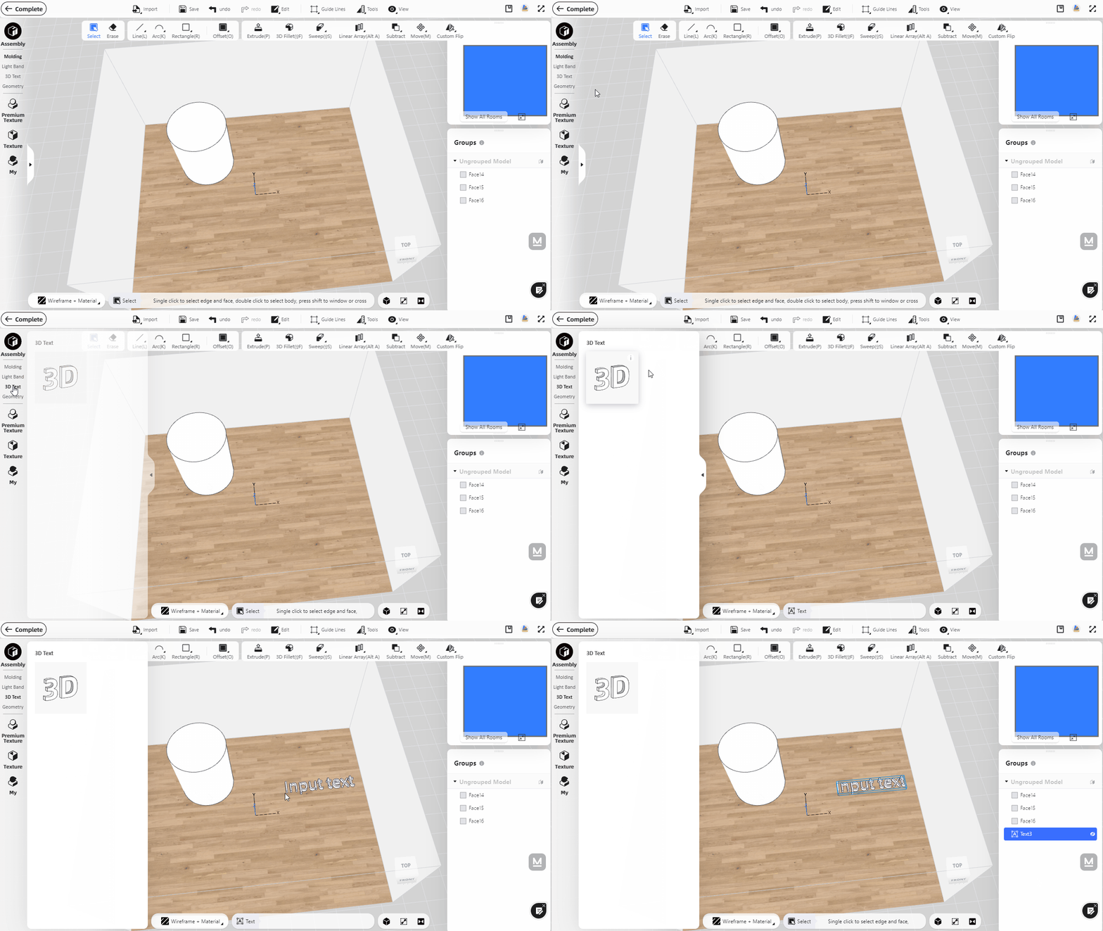
2)Use the left mouse button to select the text, click "Attach To face", and then select a flat or arc surface to snap text to it.
5.Add vertical text direction for 3D Text in Interior Modeling 2.0
Interior Modeling 2.0 now supports the creation of vertical and aligned 3D text to meet the design needs of different scenarios such as commercial scenes and storefronts.
Instruction:
1) Enter the Interior Modeling 2.0 interface, add the "3D text" from left catalog to a face.
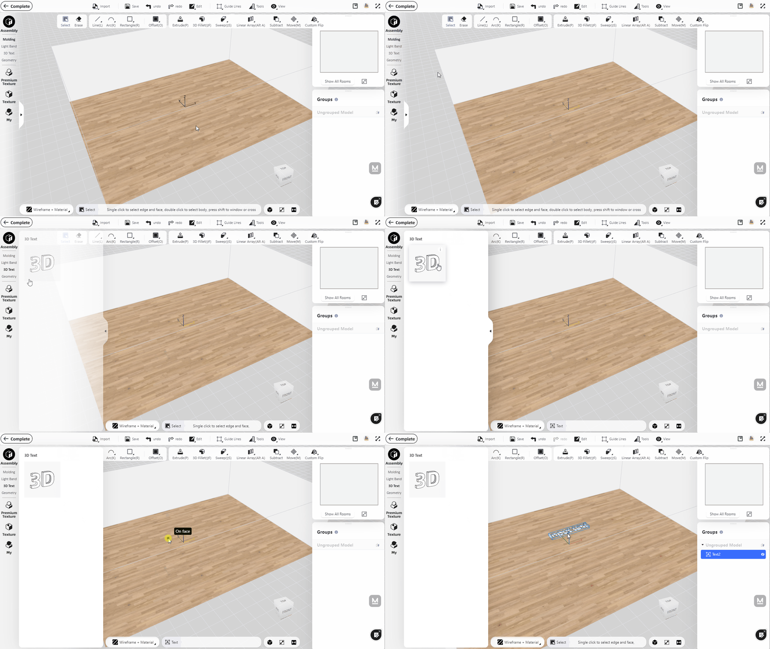
2)Enter the appropriate text information in the property panel on the right, and select "Text Direction" below to set the direction.

6.Support display of custom furniture models in Interior Modeling 2.0
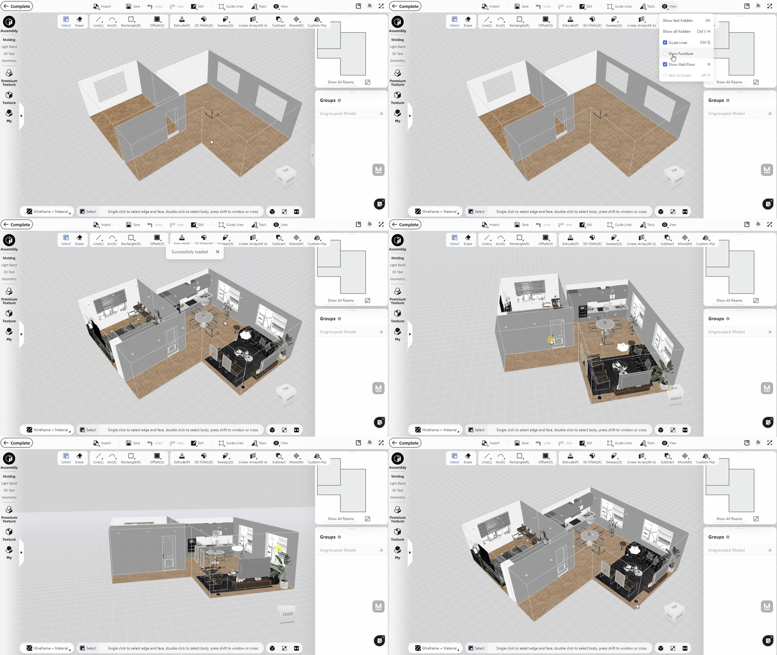
Custom furniture models can now be displayed in the interior modeling environment, which can assist designers in modeling.
Instruction:
Click "View" on the top toolbar, and check "Show Furniture" to display the furniture model.
7.Support model movement through three axes in Interior Modeling 2.0
In order to facilitate the use of high-frequency operations such as movement and rotation, we have added the function of fast rotation and movement along the X, Y, and Z axes (consistent with the operations of other modules)
Instruction:
1) After creating the model, double-click the shape to group it(shortcut key: ctrl+g).

2) The grouped models support movement and rotation along X, Y, and Z axes (consistent with the movement of furniture models)

8.Support the connection of split segments in Interior Modeling 2.0
Line segments can be custom split and connected in the Interior Modeling 2.0.
Instruction:
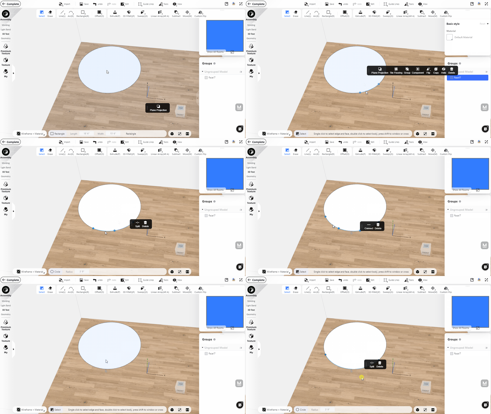
1)Split: Left-click on the line, select "Split" and drag the mouse to preview the spacing of the split line segments, or directly enter the exact number of segments in the "Segment Number" below.
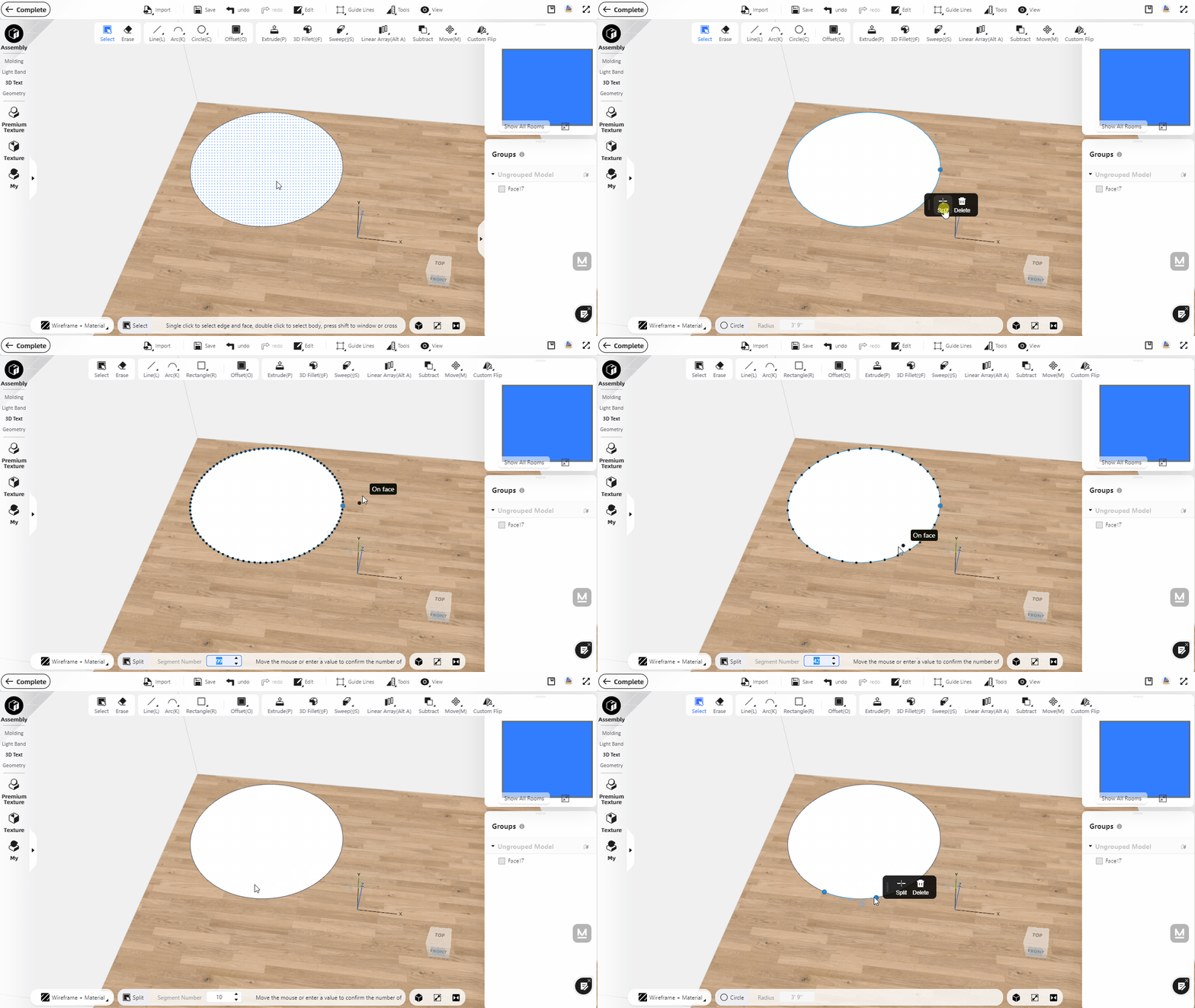
2) Connect: Select multiple split line segments by Shift, and click "Connect" to connect the line segments.
