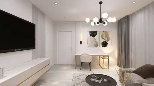
As technology continues to shape our daily routines, the latest developments like the $135 million Google Android settlement remind us of the growing importance of integrating smart gadgets into our living spaces. Designing home interiors that accommodate various devices seamlessly enhances both functionality and comfort, ensuring our environments support the evolving digital lifestyles we lead.
Common electrical CAD block import problems typically stem from mismatched units, absent layers, corrupted DWG versions, or misaligned insertion points within the block definitions. Correcting these challenges often involves verifying drawing units, auditing files, redefining block attributes, and properly adjusting insertion coordinates prior to import.
In practical drafting workflows, these issues frequently arise when symbols are sourced from diverse libraries or created under different CAD standards, causing inconsistency and import errors.
Electrical CAD blocks are intended to expedite drafting by allowing users to drag and drop symbols quickly. However, in practice, these blocks often fail to behave as expected.
Experience from numerous architectural and technical drafting projects alongside MEP teams reveals recurrent issues such as symbols appearing vastly oversized, missing attributes, refusal to load entire blocks, or crashes during DWG file imports.
Although many assume faulty blocks, the root causes usually lie in compatibility discrepancies between the block's creation environment and the host drawing.
When troubleshooting downloaded symbols, it’s beneficial to confirm their adherence to standards compatible with your CAD environment. Well-structured symbol libraries, used for technical floor plans or spatial layouts, typically help mitigate scale and hierarchy conflicts.
A key reason electrical CAD blocks fail to import is because they were developed under different CAD platforms or unit systems. Shared electrical symbols across teams and contractors can vary in scale, layer structure, file versions, or insertion conventions—conflicts that disrupt seamless integration.
The most frequent issues include scale and unit mismatches, missing layers or attributes, corrupted or incompatible DWG files, and orientation or alignment problems.
When a symbol appears disproportionally large or diminutive, it usually indicates discrepant unit measurements between the block and host drawings. For instance, inserting a block measured in millimeters into a drawing set to inches causes a 25.4 times size increase.
Correcting these scale mismatches involves standardizing unit conversions and ensuring symbol libraries correspond with project spatial dimensions. Many professionals manage this by harmonizing symbol databases with spatial planning tools, an approach similar to those employed in architectural and coordinated technical floor plans.
Missing layers or attributes often cause blocks to appear partially invisible or lose essential annotation details. Layers crucial for the block’s appearance might be absent, frozen, or hidden by layer filters, resulting in incomplete symbols.
Resolving these issues requires confirming that all required layers and attributes exist in the host drawing, adjusting filters, and sometimes manually adding or remapping missing elements.
Corrupted DWG files, especially those passed through multiple software versions, often import partially or trigger unexplained errors. Symptoms include missing entities, distorted graphics, or failed imports.
Recommended repair workflows consist of opening the files in a CAD environment, running audit and purge commands to cleanse errors and remove unused components, then resaving in compatible formats prior to reinsertion.
Misaligned electrical symbols generally result from incorrect block insertion points or rotated definitions. Because these symbols often snap to specific wiring or structural points, improper base point settings produce misplaced or incorrectly oriented blocks.
To address alignment issues, users should verify and modify insertion points within the block editor. Early visualization and coordination—like mapping spatial layouts before final placements—greatly reduces such errors during complex integrated projects.
Best practices for minimizing electrical CAD block import complications include maintaining standardized symbol libraries, coordinating closely with design teams, and adopting consistent file and unit standards throughout drafting processes.
Ignoring these standards imposes hidden costs in lost time and effort spent troubleshooting avoidable errors caused by inconsistencies.
With these insights, common import troubles such as scale discrepancies, missing layers, corrupted files, and faulty insertion points can be addressed by checking drawing units, utilizing auditing tools, and validating block attributes before integration.
For rapid troubleshooting, verify the unit match between your drawing and the electrical CAD block, run clean-up commands like AUDIT and PURGE, confirm layer existence and visibility, and inspect insertion point configurations within the block itself.
Though older DWG files often remain compatible with modern CAD systems, it is advisable to resave them in updated formats to prevent compatibility issues.
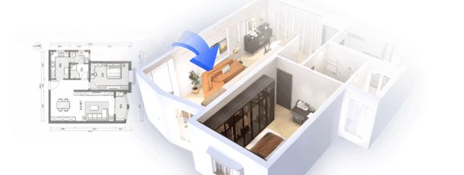
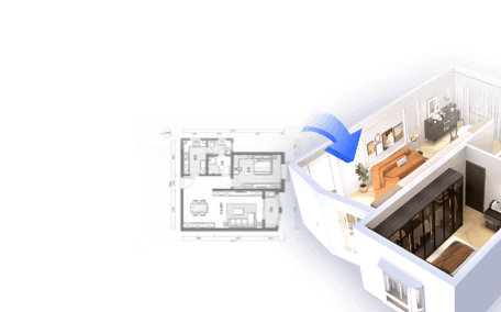
Using Homestyler can also aid in visualizing and organizing your interior designs with seamless integration of smart devices, optimizing layouts that accommodate evolving technological needs effectively.

Modern Minimalist Black Glass Walnut Console Table 3D Model

Classic White Solid Wood Three Drawer Writing Desk 3D Model

Minimalist Japandi Solid Wood Concrete Office Desk 3D Model
Homestyler is an easy-to-use online home design platform offering powerful 3D rendering, inspiring design projects, and helpful DIY video tutorials. It makes bringing your interior decoration ideas to life simple and enjoyable, whether you're a beginner or an experienced designer.
지금 무료로 디자인하세요