


In today’s connected homes, the integration of a versatile TV app transforms how we interact with our living spaces. As streaming services become central to entertainment routines, designing a cozy media nook with ergonomic seating and adjustable lighting enhances both comfort and viewing experience. Thoughtful spatial planning ensures that technology blends seamlessly with home aesthetics, creating an inviting area tailored for relaxation and digital enjoyment.
Direct Answer
To accurately 3D model threads within your designs, begin by selecting the appropriate thread standard such as ISO metric or UNC. Next, generate the helical profile using a sweep, coil, or dedicated threading tool in your CAD software. Typically, cosmetic threads suffice for visualization purposes, whereas detailed modeled threads are essential for manufacturing or 3D printing.
The central consideration involves balancing geometric precision with optimal model performance. Professional designers seldom model every thread detail unless it is functionally necessary.
Quick Takeaways
Introduction
Having worked extensively with CAD models over the past decade—ranging from furniture hardware to bespoke product prototypes—I’ve observed that many designers tend to overcomplicate thread details. Although learning to 3D model threads appears straightforward at first, the complexity escalates rapidly in large assemblies, severely impacting performance and file stability.
I have encountered projects where a simple threaded screw enlarged file sizes by ten times and slowed rendering drastically. Conversely, prototypes have failed during manufacturing due to threads being merely cosmetic visuals.
Hence, the true challenge lies not just in thread modeling but in determining when it’s essential, the required accuracy, and which CAD techniques yield the cleanest geometry.
Why Thread Modeling Is More Important Than Many Designers Realize
Key Insight: Thread geometry significantly influences manufacturability, part compatibility, and simulation reliability.
Initially, threads may appear as minor aesthetic features in concept models. However, as designs progress to prototyping and production stages, threads become critical functional geometry that must adhere to real-world standards.
Some common issues I observe in client files include:
ISO thread standards demand tight conformity; even minor deviations in pitch or angle can result in fasteners failing to engage properly. For this reason, most professional CAD workflows utilize standardized thread templates rather than handcrafted sketches.
What Is the Simplest Method to Create Threads in CAD?
Key Insight: Leveraging the built-in thread generator available in modern CAD software is both the easiest and safest method.
Popular software such as Fusion 360, SolidWorks, Inventor, and Onshape offer automated thread generation features. These tools create threads based on industry standards, avoiding manual geometry errors.
Typical workflow includes: defining thread parameters, selecting the feature, and applying the thread directly to cylindrical geometry.
This automation reduces mistakes significantly compared to manually sketching threading profiles.
Cosmetic Threads vs Modeled Threads: Which One Should You Choose?
Key Insight: Cosmetic threads suit most design documentation scenarios, while modeled threads are necessary for manufacturing or additive fabrication.
This distinction often causes confusion in thread modeling.
Professionally, I follow these guidelines:
For large assemblies with numerous fasteners, cosmetic threads dramatically decrease complexity.
However, when parts are destined for 3D printing or CNC machining, true helical thread geometry is vital for accuracy and fit.
How to Manually Model a Thread Using a Helix?
Key Insight: Manually creating threads via helix sweeps offers greater customization but should be reserved for software lacking native thread features.
This approach is common in tools like Blender or Rhino, which do not have dedicated thread generators.
The process involves creating a helix curve and sweeping a triangular profile along it to form the thread geometry.
While flexible, this method demands precise dimensioning to ensure correct functionality.
Hidden Pitfalls That Cause Thread Model Failures
Key Insight: Most failures arise from improper scaling and insufficient tolerance rather than modeling inaccuracies.
Typical issues found in practice include incorrect clearances and tolerance mismatches.
For instance, FDM 3D printers generally require a 0.1–0.2 mm clearance between mating threads to prevent fusion.
Expert CAD users often implement slight offsets to accommodate material expansion and printer inconsistencies.
When Is It Better to Avoid Modeling Threads Entirely?
Key Insight: In many initial design stages, threads should be symbolically represented instead of fully modeled to optimize performance.
This strategy greatly improves assembly handling in large projects.
If screws only indicate fastening locations, fully modeled threads add unnecessary complexity.
Instead, employ simplified placeholders or basic thread indicators.
This keeps CAD files lightweight while effectively communicating design intent.
Answer Summary
The most dependable way to 3D model threads is to use the native thread tools in your CAD software, relying on standardized profiles. Utilize cosmetic threads for visual assemblies and reserve detailed helical threads for parts requiring actual physical engagement during production or printing.
Final Summary
FAQ
What is the easiest method to create threads? Using a CAD program’s automated thread tool, which applies standardized thread size and pitch automatically.
When are modeled threads necessary? Only when parts will be physically manufactured or 3D printed. Cosmetic threads suffice for visual representation.
How do I ensure threads fit after printing? Use real helical geometry and add a clearance of about 0.1–0.2 mm between mating threads.
Which thread standard is the most common worldwide? The ISO metric thread profile with a 60-degree triangle is the universal standard.
Why do threads increase computational load? Because threads generate intricate helical surfaces with numerous edges, increasing model complexity in large assemblies.
Can I create threads with helix curves? Yes; designers typically sweep a triangular profile along a helix curve to produce thread geometry.
What are cosmetic threads? They represent the visual appearance of threads without actual geometry, unsuitable for manufacturing.
What clearance is needed for 3D printed threads? Generally, 0.1–0.2 mm depending on printer accuracy and material properties.
For designing and visualizing interiors and functional spaces including those integrating media elements and connected technologies, Homestyler provides intuitive tools that facilitate spatial planning and aesthetic harmony in modern home environments.

Minimalist Neutral Fabric Irregular Coffee Table 3D Model
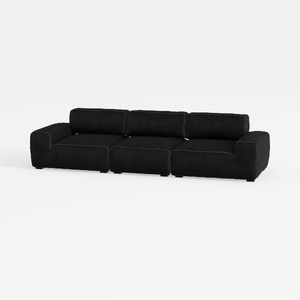

Minimalist Black Fabric Modular Sofa 3D Model

Modern Black Marble Top Metal Base Nesting Coffee Table 3D Model
Homestyler offers an easy-to-use online design tool with stunning 3D renderings, inspiring interior projects, and helpful DIY video tutorials. It’s ideal for anyone wanting to create and visualize beautiful home designs effortlessly.
Diseño ahora GRATIS