- Building element: roof edge, window head, stair landing, slab edge.
- Assembly: wood frame, masonry, rainscreen, concrete.
- Condition: exterior corner, opening, change of material, or transition.
- Drawing scale: often a larger-scale section or axonometric for complex junctions.
A plan can look polished and still leave a builder asking the expensive question: how, exactly, do these parts meet? That is where construction details earn their keep. A clear detail drawing explains the layers, dimensions, and transitions that a floor plan cannot show. If you are collecting construction details for a studio project, a renovation, or a first set of permit drawings, the goal is not to copy a pretty section. It is to find a reliable reference, understand its logic, and adapt it to your own assembly.
Below are nine useful places and drawing types to start with, followed by a method for checking whether a detail belongs in your plans. Treat every reference as a design aid, not a substitute for local codes, engineering, or manufacturer instructions.
Start with the junction, not the drawing library
Before searching, name the problem you need to solve. “Wall detail” is too broad; “wood-framed exterior wall at a window sill” is useful. Construction details are most helpful when they answer a specific junction question: where does water go, what carries the load, how does insulation continue, and what dimension controls the finish?
A good reference usually shows more than a silhouette. Look for a clear cut through the assembly, material layers, a scale or dimensions, and enough context to understand how the detail connects to the larger building. A detail that omits the air or water control layer may still be useful for appearance, but it is not a complete envelope solution.
Use this quick search formula:
For example, search for “ventilated rainscreen window head section” rather than “modern house detail.” The narrower phrase tends to surface drawings with a real assembly behind them. I also keep a small reference folder organized by junction, not by project; it is much faster to find a sill detail when the next design needs one.


9 construction details references worth collecting
These are reference categories, not ready-to-paste specifications. Compare at least two sources when the junction affects structure, fire safety, or weather protection.
- Building-code and government guidance. Start here for required clearances, fire separation, accessibility, and climate-specific envelope principles. Codes establish minimum requirements; they rarely provide every project-specific drawing. Confirm the edition adopted by your jurisdiction.
- Building science publications. Technical guides on moisture, air leakage, thermal bridging, and ventilation help explain why a layer is placed where it is. They are especially useful for roof-to-wall and foundation transitions, where a small gap can undermine an otherwise sensible assembly.
- Manufacturer installation manuals. For windows, roofing, cladding, membranes, and insulation, the manufacturer’s current instructions can clarify compatible components and fastening patterns. Match the product and system exactly; a detail for one window series may not apply to another.
- Architectural detail books and technical handbooks. These are strong for drawing conventions and common junction logic. Check publication date and climate assumptions. Older references can teach linework while being outdated on insulation, membranes, or code requirements.
- Architecture school and studio repositories. Student work can offer clear diagrams and inventive spatial solutions. Use it for visual thinking, not as proof of structural adequacy or code compliance. Trace the assembly and verify every critical layer elsewhere.
- Professional project case studies. Published projects often show how a design intent became a built junction. Look for sections, construction photos, and notes that explain the material sequence. A beautiful image alone cannot tell you how the flashing laps.
- Open technical drawing libraries. Searchable CAD or BIM libraries can save drafting time, particularly for standard components. Check units, scale, file version, and whether the object represents a generic placeholder or a specific tested product.
- Structural engineer details. For beams, connections, retaining walls, stairs, and unusual spans, use project-specific engineering. A generic detail may show the concept, but member sizes, anchors, and reinforcement depend on loads and site conditions.
- Your own verified project archive. After a detail has been reviewed and built, keep the approved drawing, product data, and site notes together. Record what changed in the field. This becomes a more useful reference than a folder of attractive but context-free images.
| Reference type | Best for | Check before adapting |
|---|---|---|
| Code or public guidance | Minimum requirements and clearances | Local adoption and climate zone |
| Manufacturer manual | Product-specific installation | Exact model and compatible components |
| Detail book or case study | Drawing logic and precedent | Date, assembly, and project context |
| CAD/BIM library | Standard geometry | Scale, units, and product validity |
| Engineer’s drawing | Structural connections | Project loads and professional approval |


How to adapt a reference without copying its mistakes
A reference becomes useful only after you test it against your project. I like to mark up a copy in a different color before redrawing it. That simple step makes assumptions visible: which layer is continuous, what dimension is fixed, and what needs a local professional’s review.
Work through this sequence:
- Confirm the conditions. Note climate, exposure, building type, structure, and whether the detail is interior or exterior. A warm-climate wall and a cold-climate wall may need different vapor-control strategies.
- Trace the control layers. Follow water, air, thermal, and vapor control across the junction. If a line stops at the window or roof, ask how it continues in the actual assembly.
- Check dimensions and scale. Verify thicknesses, clearances, slopes, and overlaps against the project and product data. Do not scale a screenshot and treat the result as a dimension.
- Coordinate trades. Confirm that framing, flashing, insulation, cladding, and finish work can be installed in a sensible order. A detail that requires impossible access will be changed on site.
- Flag decisions. Mark unresolved structural, fire, waterproofing, or code questions for the architect, engineer, or building official responsible for them.
For a window sill, for instance, the drawing should make the drainage path legible, show how the sill pan connects to the wall’s water-control layer, and avoid trapping water behind the finish. The exact products and dimensions depend on the selected window and wall system. That is why a generic diagram is a starting point, not a construction instruction.
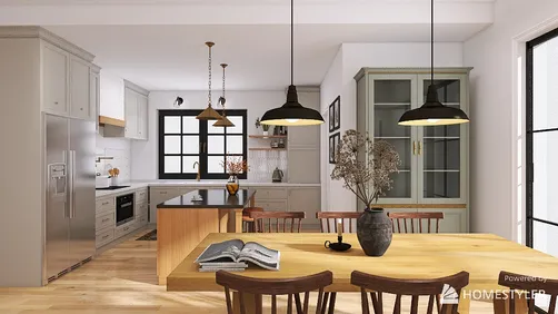
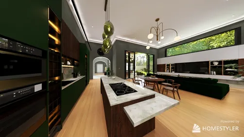
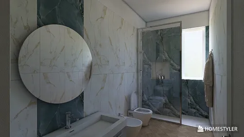
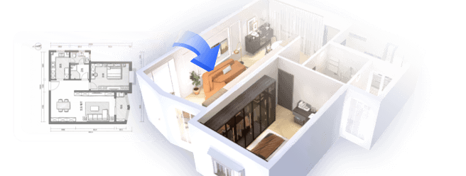
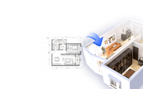
If you are still shaping the room around a junction, a quick 3D study can help you check proportions and finish relationships before polishing the technical sheet. Homestyler is useful for previewing how a window, wall finish, and interior layout read together; keep the construction assembly itself in your technical drawings.


Make the drawing readable to someone building it
A technically correct detail can still fail if the sheet is hard to read. Use a consistent line-weight hierarchy: cut elements bold, objects beyond lighter, and dimensions and leaders clear of the assembly. Label materials specifically enough to distinguish them, but avoid turning the drawing into a paragraph. Put longer performance notes in a keyed specification or schedule.
A practical detail sheet should usually include:
- A title that names the junction and its location.
- A reference bubble linking the detail to the plan or section.
- A scale, units, and key dimensions.
- Material layers and the direction of water drainage where relevant.
- Notes for interfaces, fasteners, and installation sequence when needed.
- A revision date or issue status managed through the project’s normal document process.
Do not rely on color alone to distinguish layers; drawings are often printed in grayscale. Likewise, avoid tiny text that looks fine on a monitor but disappears on a half-size print. I prefer one enlarged, well-composed detail over a crowded sheet of miniature sections. If a contractor has to guess which line is the membrane, the drawing needs another pass.
For early design, a simple section can communicate intent. For permit or construction documents, the level of detail should match the project scope and local requirements, with qualified professionals reviewing regulated or high-risk conditions. Homestyler can help you test the visual relationship between materials and spaces, while the technical set carries the buildable information.
A short checklist before a detail goes into your plans
Before issuing a drawing, ask: Does it match the actual structure? Are the products identified or clearly specified? Can the water and air-control layers be followed without guessing? Are dimensions coordinated with plans, elevations, and schedules? Has the right professional reviewed structural, fire, and waterproofing decisions?
Keep the source and adaptation notes with the drawing. That record helps a future reviewer understand why a layer or dimension changed, and it prevents a generic reference from quietly becoming an unverified instruction. If a detail depends on a manufacturer’s system, save the relevant product documentation alongside it and confirm that it is current when the project is issued.
Built on technology originally developed at Autodesk, Homestyler empowers anyone to design beautiful, realistic spaces in minutes. Join over 20+ million registered users (platform data, 2026) who have already discovered a smarter way to plan, visualize, and bring their dream homes to life — all from the comfort of a browser.
Construction details are not decoration at the edge of a plan set. They are where design intent meets materials, weather, tolerances, and the sequence of work. Start with one difficult junction, find a reference that explains its logic, and redraw it for the conditions you actually have. When the spatial design is still evolving, preview the room and material palette in Homestyler, then keep the final assembly decisions in coordinated technical drawings reviewed by the appropriate professionals.
Дизайн сейчас бесплатно