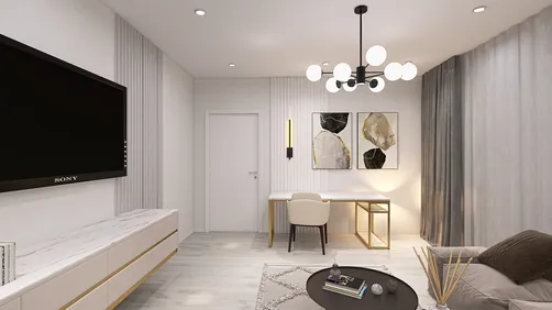
In my designs for plant rooms, I prioritize creating spaces that are serene, organized, and capable of withstanding pressure. When unexpected situations arise—like chiller failures, pump issues, or late-night alarms—having a well-thought-out layout along with clear protocols ensures that minor glitches do not escalate into major system failures. The overarching objective is to establish reliable airflow, ensure equipment is easy to access, and implement robust controls while also future-proofing the setup to accommodate shifts in needs. Utilizing tools like Homestyler can facilitate effective design planning.
The initial design choices are heavily influenced by performance and health compliance metrics. For instance, the WELL v2 standard advises maintaining indoor temperatures between 20–24°C with humidity levels at 30–60% to ensure comfort and support respiratory health; therefore, the plant must consistently supply stable ventilation amidst varying loads. While ASHRAE guidelines are standard, leveraging actual workspace data enhances strategic sizing. Research from Herman Miller indicates a direct correlation between thermal comfort and productivity, noting that work efficiency diminishes when environmental conditions exceed acceptable ranges. Additionally, to aid visibility, adhering to IES illumination guidelines, typically ensuring 300–500 lux in technical environments, is crucial for technicians to effectively monitor gauges and labels without experiencing glare or eye strain.
Effective capacity planning hinges on establishing both diversity and redundancy. In critical commercial spaces, I aim for an N+1 redundancy for essential pumps, along with a spare capacity of at least 20–25% in electrical systems, enabling them to handle peak demands and accommodate upgrades. Studies by Steelcase indicate that comfort and reliability foster trust within environments; a dependable plant not only preserves operational integrity but also minimizes reactive maintenance. It’s vital to devise your load profile based on actual occupancy, envelope performance, and equipment usage schedules rather than merely following rough tonnage estimates. Moreover, being mindful of low-load conditions can help prevent short cycling, which can lead to compressor damage and increased energy consumption.
Space Planning and Circulation
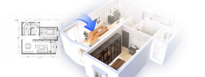
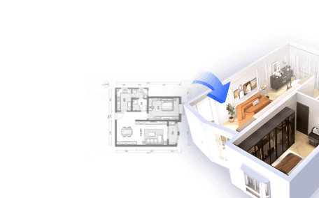
Adequate clearances should be considered essential for maintaining uptime. Ensure that there’s sufficient swing and pull-out room for tube bundles, strainers, and belt drives. Minimum service aisles should measure between 900–1200 mm in width, with 1500–1800 mm clearances around major equipment for safe rigging and maintenance activities. When planning from shell-and-core specifications, utilizing a room layout tool can assist in visualizing pipe runs, coil retrieval paths, and crane access routes prior to installation.
room layout tool
Maintain uninterrupted egress, ensure that doorways are free from pinch points, and design clear divisions between wet and dry areas—position chillers and pumps over floor drains while keeping panels, BMS racks, and VFDs in dry sections equipped with drip shields.
Mechanical Zoning and Equipment Placement
Organize equipment according to their function and operating temperatures: place chilled water headers centrally, situate condenser water lines on the perimeter for efficient heat rejection, and orient air-handling units to minimize duct pressure losses. Be sure to maintain direct suction line runs to pumps (5–10 pipe diameters) and align strainers for easy access to baskets. Dedicate space for chemical dosing that includes spill containment and an eyewash station, ensuring it is distanced from electrical components.
Pipework, Valving, and Isolation Logic
Implement manifold designs that feature proper isolation and bypass systems: this includes using triple-duty valves on pump discharges, butterfly valves for isolation on headers, and pressure-independent control valves at key load points. Position pressure taps and drain ports at every high and low point to facilitate future commissioning success. To reduce human errors, employ color-coded pipe bands indicating flow direction and service identity. Ensure flexible connectors are positioned at vibration spots, and verify pipe supports can withstand both static and dynamic loads, particularly in vertical applications.
Electrical and Controls Strategy
Ensure that electrical panels are installed above any potential wet zones and far from floor drains. Clearly separate normal and emergency power feeders; keep cable trays well-organized and labeled per circuit needs. Variable frequency drives require sufficient ventilation—be sure to check the manufacturer's specified clearances and heat load tolerance. In terms of control systems, delineate safety interlocks from optimization logic. Equip each significant asset with local hardwired controls for run/stop and hand-off-auto settings. Additionally, track key performance metrics such as delta-T, kW/ton, differential pressure across pumps, and condenser approach, while maintaining logs of alarms for future analysis.
Lighting, Visibility, and Safety
Aim for uniform lighting levels of 300–500 lux while avoiding harsh contrasts that can obscure leaks or mislead gauge readings. IES standards recommend glare control; therefore, deploy diffused LED fixtures while incorporating task lighting at access points such as panels and strainers. It’s imperative that emergency lighting complies with corridor egress codes, alongside luminaire placements that enhance visibility of signage and floor gradients. Utilize reflective labels, large print identifiers, and asset IDs facing primary service aisles for clarity. Furthermore, anti-slip coatings and high-contrast stair nosing should be used to prevent accidents in wet conditions.
Ventilation, Heat Rejection, and Acoustic Comfort
Given that plant rooms tend to generate considerable heat, it is vital to provide dedicated ventilation systems that are sized according to equipment heat loads and local air change regulations. Ensure clear paths for condenser air and maintain minimum distance from walls, while designing exhaust systems to prevent recirculation into intakes. Acoustic management is critical; place pumps and chillers on inertia bases, utilize resilient mounts, and treat hard surfaces with absorptive panels to effectively minimize sound pressure levels. A quieter environment not only decreases operator fatigue but also enhances diagnostic accuracy.
Drainage, Housekeeping, and Materials
Integrate continuous trench drains near chillers, chemical dosing stations, and filter chambers; floors should slope toward these drains, and joints should be sealed to resist chemicals. When selecting materials, prioritize maintenance suitability: epoxy flooring that is highly resistant to chemicals, galvanized or stainless steel supports in wet areas, and powder-coated surfaces for corrosion resistance are key. Ensure hose bibs, mop sinks, and spill kits are easily visible and accessible.
Thermal Performance and Energy Metrics
Vigilantly track kW/ton and delta-T measurements; low delta-T values (below 8–10 K in chilled water systems) may indicate coil issues or balancing discrepancies. Enhancing these metrics can significantly reduce plant energy consumption. Stage chillers for optimal efficiency to maximize part-load performance, provided that control systems are properly calibrated. Monitor condenser approach values to quickly identify fouling. In structures that aim for WELL certification, ensure thermal and humidity sensor calibrations are accurate by cross-referencing with handheld devices, as even minor drifts can skew Building Management System decisions.
Human Factors, Ergonomics, and Workflows
Given that operators spend substantial time in these areas, it is crucial to design environments that prioritize human ergonomics as much as machine functionality. Install valves at waist height where feasible, reduce the need for ladder use, and position sight glasses and gauges at heights ranging from 1200 to 1500 mm for ease of viewing. Ensure components that require frequent servicing are accessible from the aisle side. Organizing tasks—such as water treatment, filter replacements, and electrical checks—into clearly defined zones minimizes cross-contamination and enhances response efficiency. Workflow processes should be visually communicated with wall-mounted, laminated schematics.
Risk, Redundancy, and Maintainability
Implement N+1 redundancy for crucial pumps, dual strainers for headers, and service isolation configurations that allow partial plant function during maintenance activities. Plan rigging routes from the outset to facilitate the replacement of major components, like chillers, without requiring extensive disassembly. Store spare parts and tools in designated cabinets and keep logs of service intervals on visible tags. Ensure dampers and valves are engineered for fail-safe positions, and double-check that emergency power systems can maintain essential loads through validated transfer protocols.
Commissioning and Future-Proofing
Commissioning represents a pivotal phase in the project lifecycle. Ensure calibrated testing ports, accurate as-built documentation, and a clear operational sequence are available. Monitor systems for a minimum of 4–6 weeks under varying load conditions to optimize settings. For future-proofing, reserve space for additional pads, stub-outs for headers, and allocate at least 20% spare input/output capacity in control systems. Maintain ample margins in cable trays and reserve spare MCC buckets for potential expansions.
Common Pitfalls I Avoid
- Cramming equipment into attractive designs that overlook actual service clearances
- Allowing wet and dry zones to overlap, risking nuisance trips and corrosion
- Positioning VFDs in hot locations without proper ventilation
- Failing to label valves and pipes, hindering emergency response times
- Neglecting condensate and maintenance water drainage, leading to hidden slip hazards
FAQ
Ensure to plan for 1500–1800 mm service clearances surrounding major equipment and 900–1200 mm for aisles. Validate rigging and pull-out specifications based on manufacturer guidelines, especially regarding tube bundles and strainers.
Aim for 300–500 lux of general lighting while ensuring uniformity. Implement task lighting specifically at panels and service points. Adhering to IES guidelines helps reduce glare and improves visual accuracy.
Maintain an N+1 redundancy scheme for critical pumps and control systems, including bypass configurations for major headers. Ensure that emergency power remains available for vital loads and routinely verify transfer procedures.
Optimize staging for part-load efficiency, vertically monitor both kW/ton metrics and delta-T readings, adjust coils, and clean heat exchangers to minimize condenser approach temperatures.
Establish setups in dry zones away from drains and any splash risks while ensuring adequate ventilation and service clearances according to manufacturer recommendations. Distinctly segregate normal and emergency feeds for straightforward maintenance procedures.
Design with foresight by reserving space for pads, implementing header stub-outs, and allowing for 20–25% spare capacity in electrical distribution systems. Maintain extra input/output and cable tray space to accommodate future control expansions.
Size ventilation systems to cater to equipment heat loads while abiding by code-mandated minimum air changes, ensuring clear condenser air pathways to deter recirculation issues.
Utilize precise testing ports, verify operational sequences, and track performance metrics—such as delta-T, kW/ton, and approach temperatures—for several weeks while calibrating sensors against reliable handheld devices.
Employ inertia bases, resilient mounts, and sound-absorptive treatments effectively. Separate noisy devices from control regions, and avoid hard surfaces placed parallel to each other that intensify ambient noise levels.
The WELL v2 framework suggests maintaining relative humidity levels between 30–60% for optimal comfort and health; ensure that selected cooling coils and control processes can uphold these ranges without leading to over-drying or condensation problems.

Minimalist Light Gray Fabric L Shaped Sectional Sofa 3D Model

Minimalist Beige Fabric L Shaped Sectional Sofa with Throw Pillows 3D Model

Triple Wide 5-Tier Bookshelf, 70.87" L x 79.13" H
Discover your home's potential with Homestyler! This user-friendly online design platform offers an intuitive design tool, stunning 3D renderings, diverse design projects, and informative video tutorials. Easily create and visualize your dream spaces, making home design accessible and inspiring for everyone.
Progetta ora GRATIS